Create a Rig
This document shows how to set up a basic rig in Blender. If you want to get more familiar with some rigging concepts, check out The Rig: Basic Concepts .
Adding the Armature #
First of all, you’ll need to import your 3D model into Blender or, if you did it in Blender already, just open your blend file. In object mode, press Shift+A and select Armature on the menu, like show below. Then, in Object Data Properties, under Viewport Display, toggle In Front, so you can see the bone through the mesh. Mesh and armature should be aligned, so make sure the model is well positioned in the center of the world before adding the bones. The origin of the armature should be at 0,0,0 (X,Y,Z).
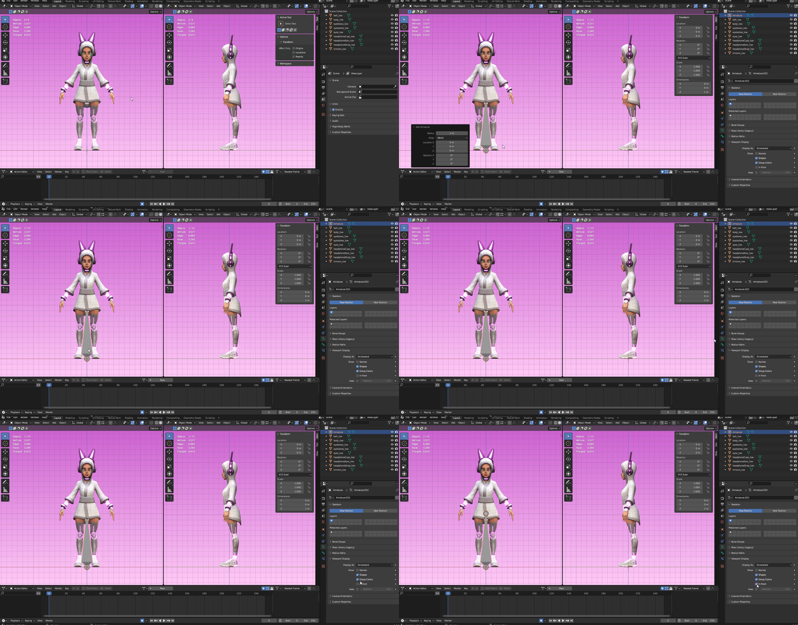
Adding an armature and showing it through the mesh.
Editing the Armature #
After adding the Armature object, select it and go to Edit Mode. Here is where you add the other bones by extruding the original one (press E), duplicating it (Shift+D) or simply adding a new one with Shift+A. The skeleton should follow the shape of the model, like a real skeleton. Bones can be scaled, grabbed and rotated and they have two parts: the head and the tail. The head is the pivot point, which means that rotations and scale will start from there. That also means that it’s where the mesh deformation will happen, so position the bones as centered in the mesh as possible.
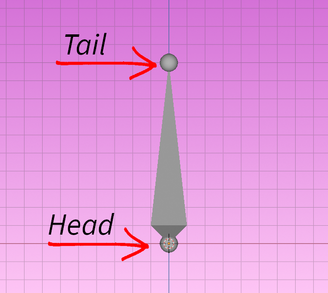
Bone structure.
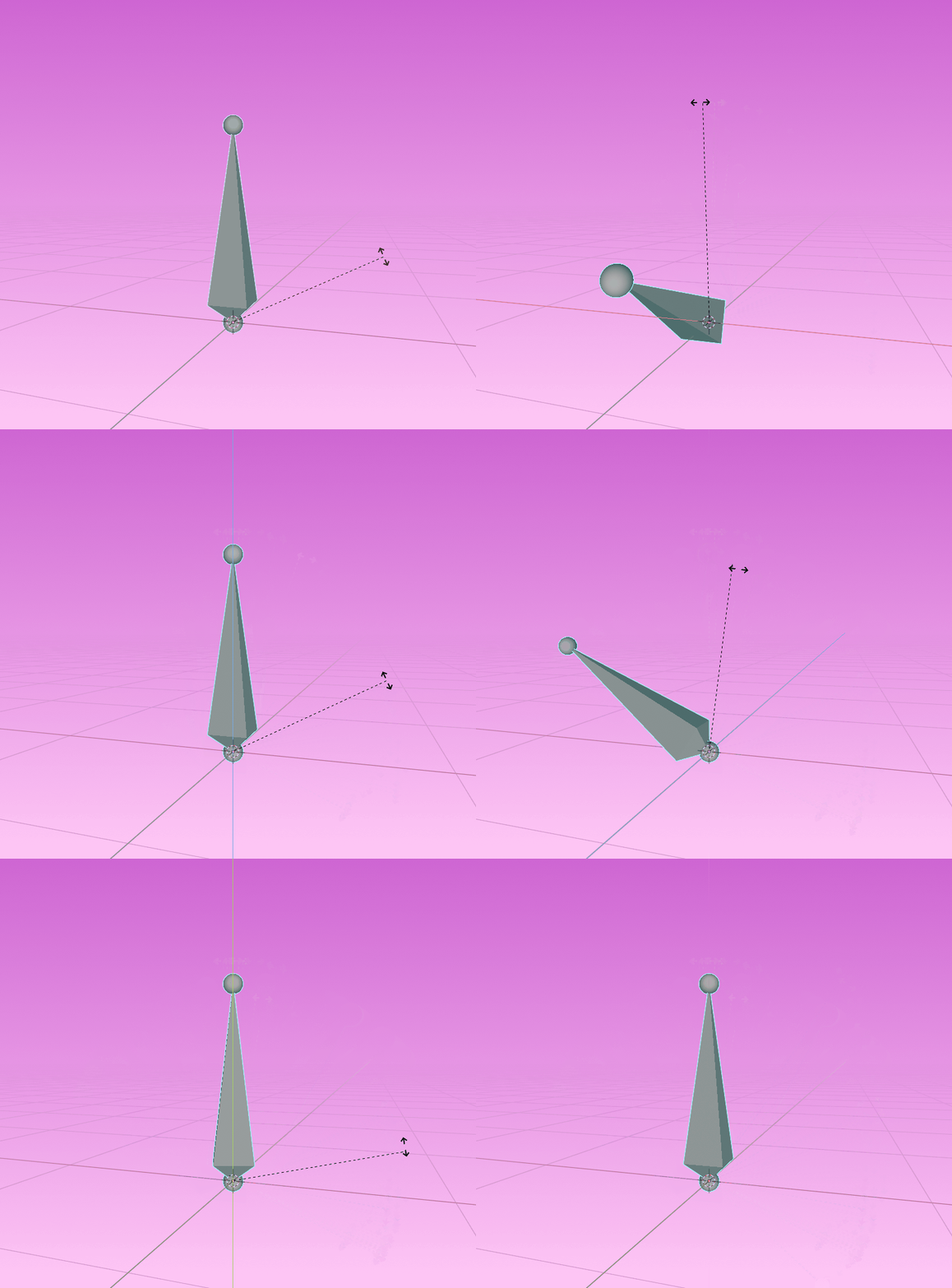
Bone rotating from its pivot point.
There’s no need to worry about creating bones for the right and left side for now. Focus on creating only one side first.
Renaming the Bones #
Something really important to keep in mind is renaming all your bones properly, according to Blender’s naming convention . This will not only keep everything organized, but also make it possible to mirror poses and weight paint. You could just rename it as the body part it represents, like Spine_01 or your could be more specific and call it DEF_spine.001 (DEF stands for deforming bone, so you kow that this bone is from the deforming hierarchy).
Bone Orientation #
Before moving on, you should check your bone orientation. You can do that by going to Object Data Properties and under Viewport Display, toggle Axes. This will make the bones’s axes visible, so you can check if they are going to rotate in the proper direction.
The axes should be aligned with the direction in which you want the bones to rotate. If it feels a little off, select the bone and, in the Item Transform menu on the right of the viewport, adjust the Roll until the orientation feels right.
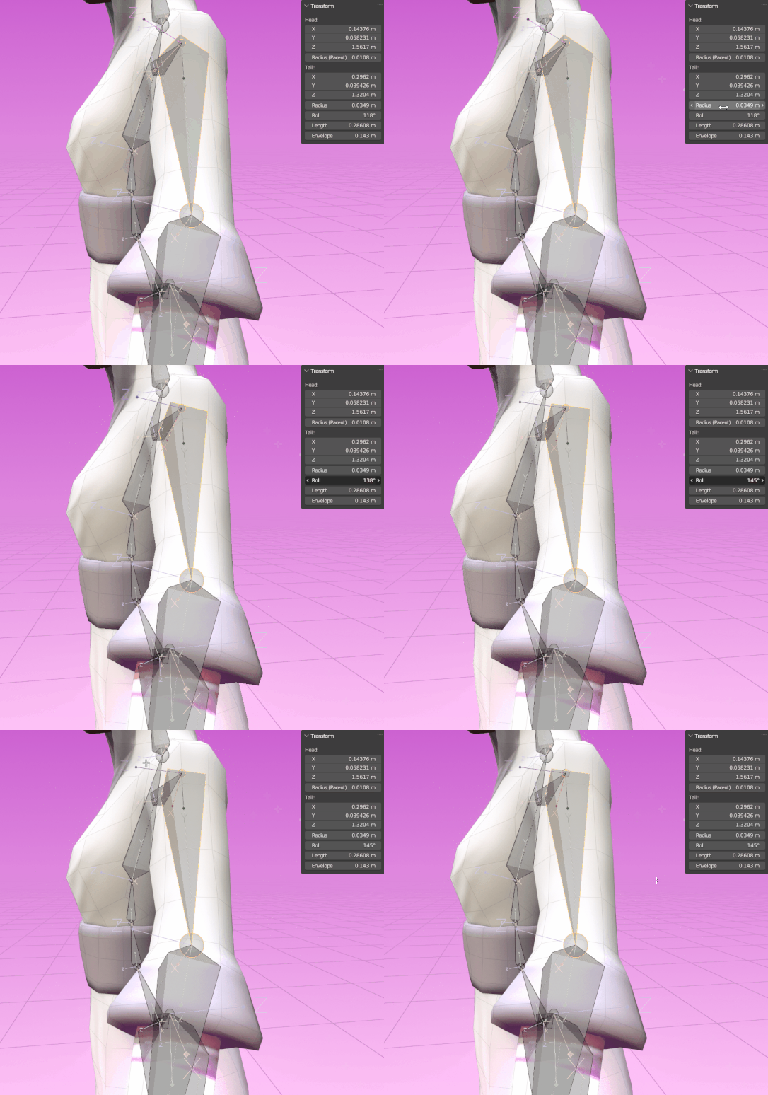
Fixing the bone roll.
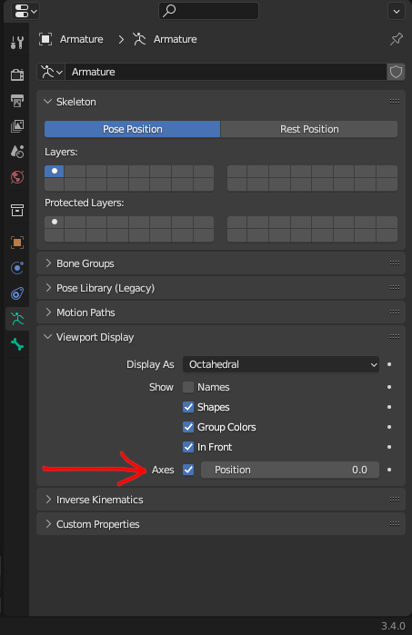
Toggle Axes on so you can see the direction in which the bone will rotate.
Fixing the bone roll is especially important for fingers, so all the joints bend in the same proper direction. You don’t have to do it for all the bones in a finger though, just get one of them right. Then, select the ones you want to fix first and the one with the proper roll last, go to Armature > Bone Roll > Recalculate Roll > Active Bone and they will all have the same roll. Or you can just press Shift+N > Active Bone. This can be used in many situations where you have a long chain of bones, like a tentacle, a tail, a long pony tail or a mechanical arm.
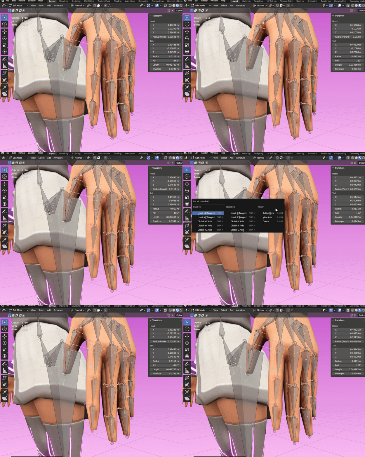
Press Shift+N to recalculate the bone roll.
Mirroring the Rig #
You don’t have to create bones for both sides. Just do one side first and when you’ve fixed all the naming and bone orientation, select all the bones you want to mirror, click with the right mouse button and select Symmetrize. That way all the bones will be mirrored properly, with the right orientations. Remember that in orderfor this tool to work, bones need to be named according to Blender’s naming convention. If there is a lower or upper case “L”, “R”, “left” or “right”, Blender handles the counterpart correctly.
Some examples of proper naming convention:
- Hand_L –> Hand_R
- Hand.L –>Hand.R
- HandLeft –> HandRight
All the examples above are valid, but chose only one and keep it consistent through the rig.
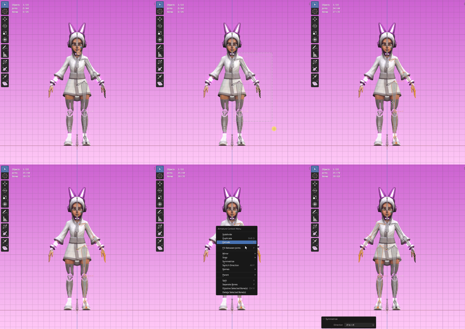
Use the Symmetrize option to mirror your bones.
⚠️ Attention! Symmetrize will only work if the bones are renamed properly. If it doesn’t mirror properly you might want to double check the bones’s names.
Skinning #
Skinning is the process of binding the mesh to the armature. To do so, in Object Mode, select the mesh, then the armature and press CTRL+P > Armature Deform > With Automatic Weights. Then, go to Pose Mode and test different poses to test the mesh deformation. Most of the time it will need some adjustments, as seen below.
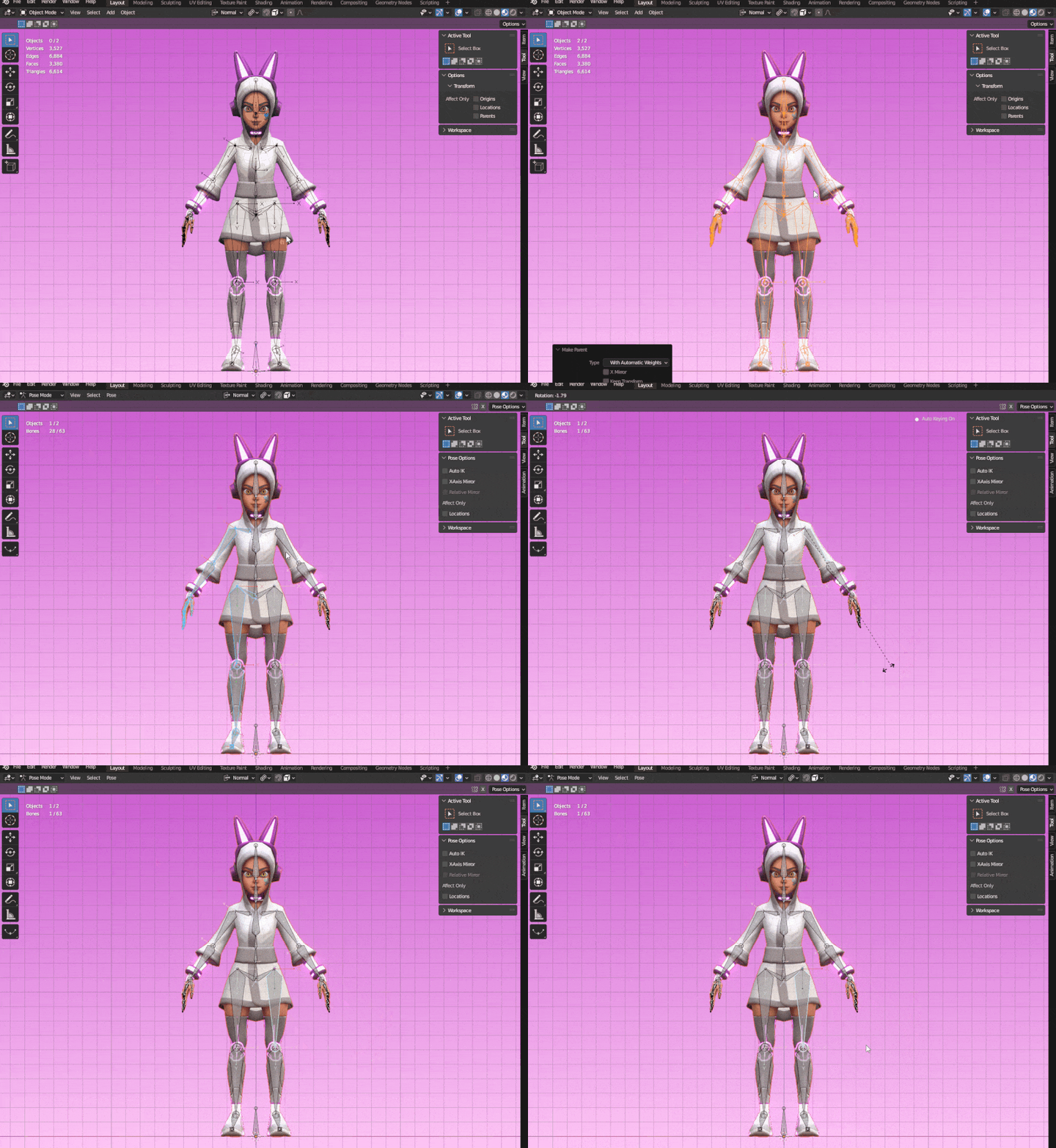
For the Skinning, make the mesh child of the armature by pressing CTRL+P and test it in Pose Mode.
If you feel like a bone has been misplaced or that the pivot point is not accurate, you can always go back to the armature’s Edit Mode and adjust it. This won’t affect the skinning at all and you can always use Symmetrize to mirror the changes.
To fix weird deformations, go to Object Mode, select the mesh and go to Weight Paint. In Object Data Properties you will find the Vertex Groups.
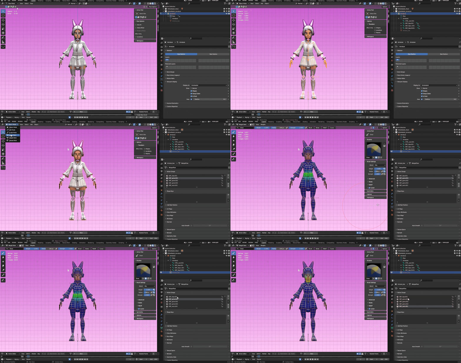
Edit a bone’s influence in Weight Paint.
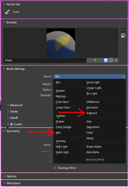
Before you start editing, to have you weight paint automatically mirrored as you paint, toggle Mirror Vertex Groups and select X in Mirror under Symmetry (in Blender 3.4.0) To edit the influences, select the vertex group one you want and, in the Tool menu, under Blend, switch between Add and Subtract according to your needs. You can also change the size, weight and strength of the brush.
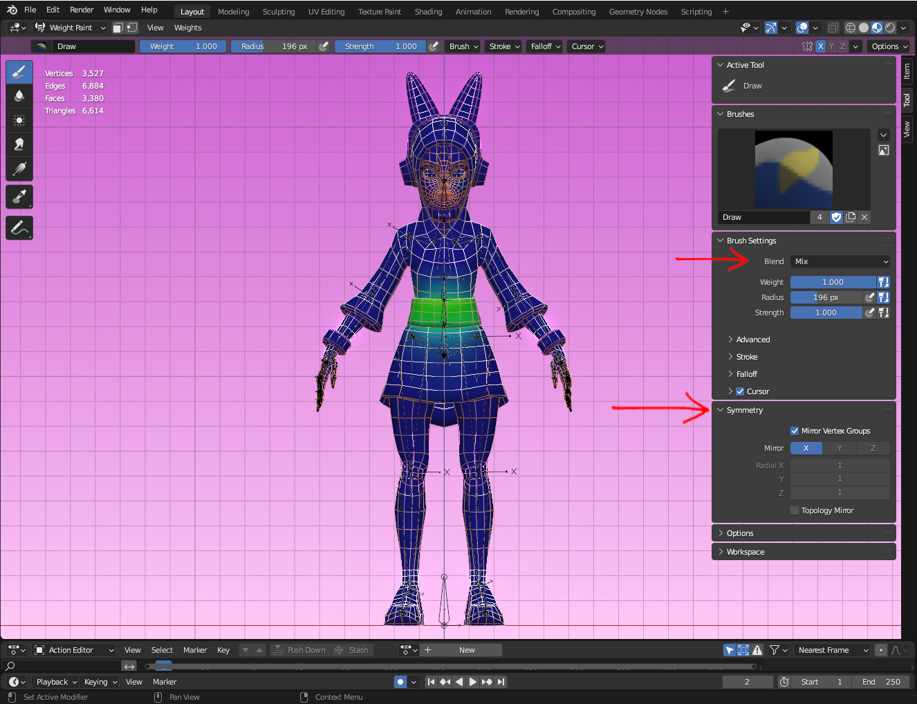
Change the Blend to add or remove influence. Make sure Symmetry is right.
Use the Blur tool ont the left side of the screen to smooth the weight paint and make it more even.
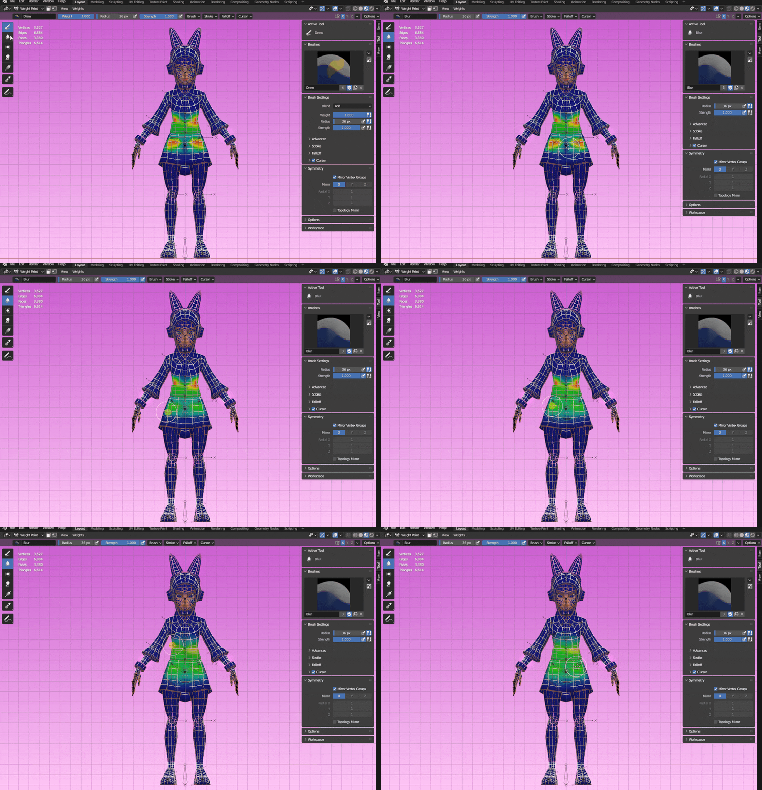
Blur Tool.
Setting Up the IK #
IK is essential when you want something to stay in place. The best example of its use is on legs, but it can be adopted in a variety of situations, like in the examples below:
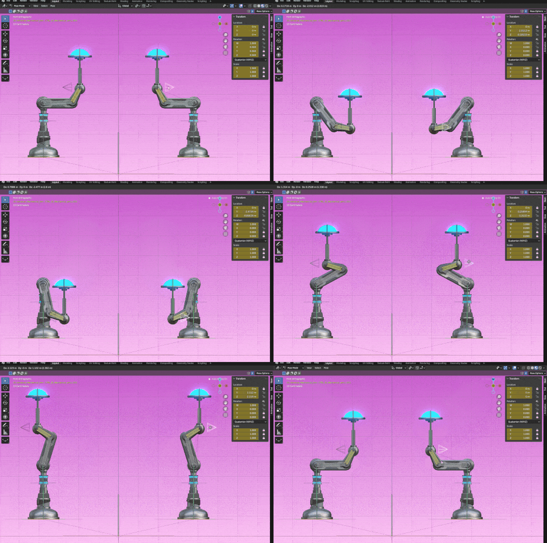
IK use in a mechanical arm.
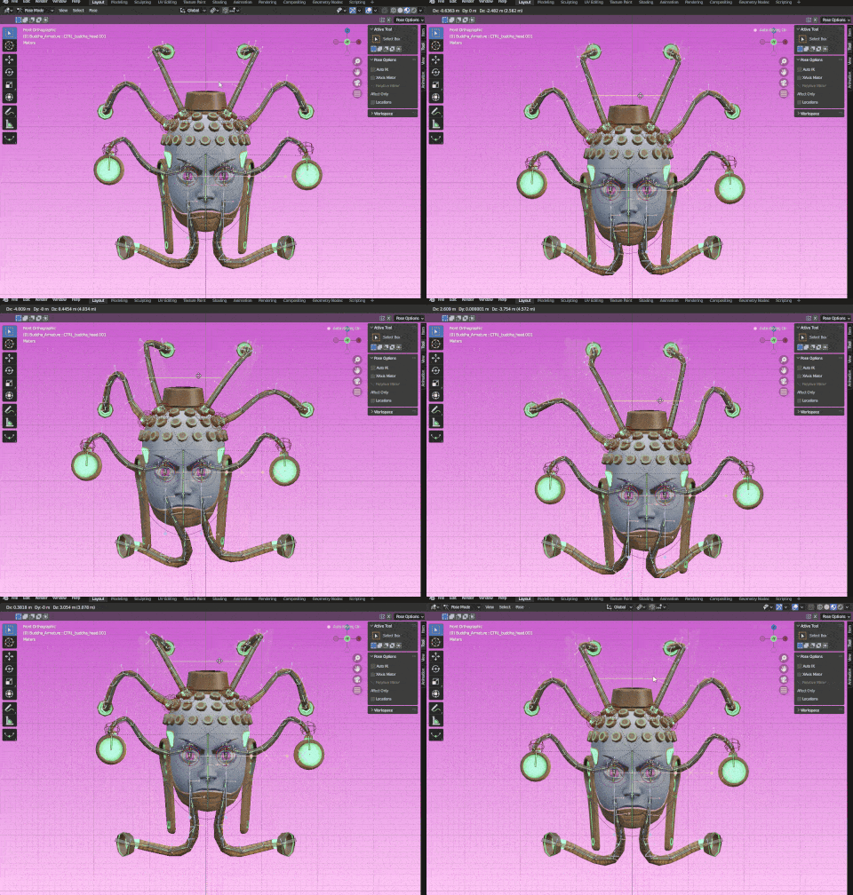
IK use in cables.
Since it’ll change the hierarchy of bones, it’s best to keep it as a separate setup. So the first thing you need to do is duplicate the bone chain that will be affected by the IK. Let’s use the leg as an example. Select the bones, press Shift+D to duplicate them and move them to a different layer by pressing M and selecting a different slot for it.
Remeber to rename the duplicated bones, adding IK to the name so you know they are part of the IK setup. And since they shouldn’t deform the mesh, select all them and in Bone Property, press and hold Alt and uncheck Deform.
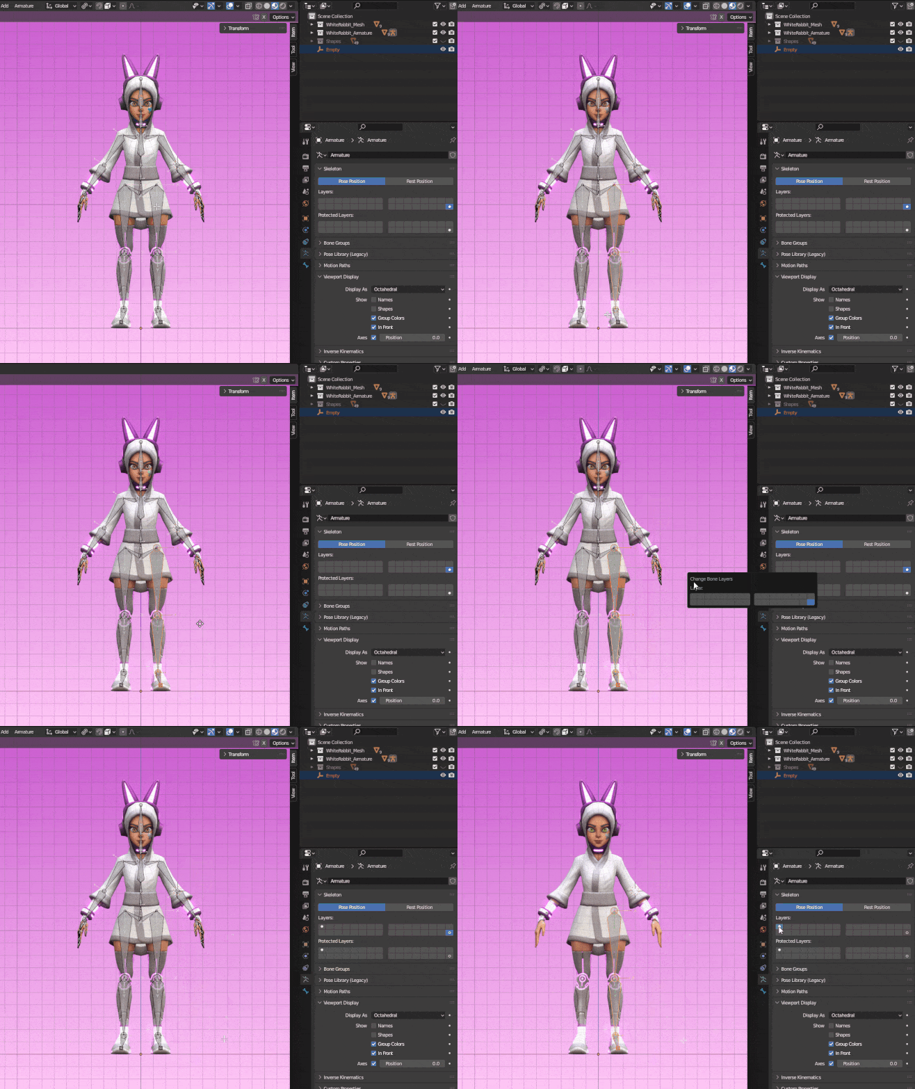
Duplicate the bones and move them to a different layer.
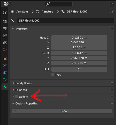
Select all the IK bones and, while holding Alt, uncheck Deform.
Next, you’ll need to create a bone that’ll drive the IK chain. Select the head of the foot bone and extrude it on Y. Then, press Alt+P to unparent it because the IK bone can’t be part of the chain and can’t be connected to other bones. You’ll need to make the foot a child of the IK, so select the foot bone first and the IK bone last and press CTRL+P > Keep Offset.
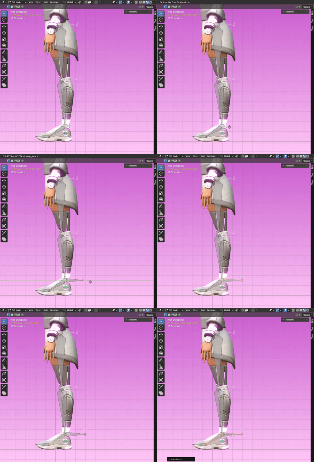
Creating an IK bone.
In Pose Mode, click on the shin bone, press CTRL+Shift+C and select Inverse Kinematics. It will look all messed up, but don’t worry, it will be fixed once you change a few settings. With the shin selected, got to the Bone Constraint Properties as shown below.
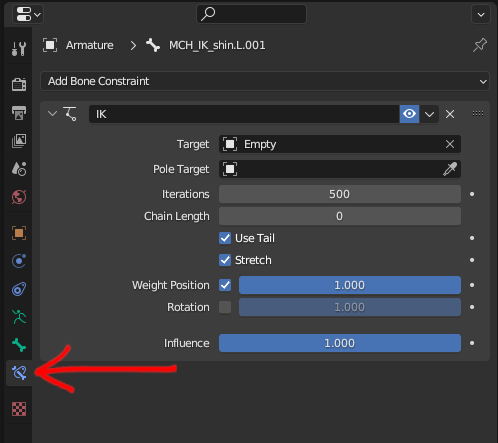
In Bone Constraint Properties you can edit the IK settings.
For the Target, select Armature. Once you do that, an option called Bone will appear under Target. For that, select the IK bone you created. In Chain Length you will set the number of bones that should be affected by the IK. Since we are doing a leg, we want it to affect the shin and the thigh, so set it to 2.
Pole Target #
The Pole Target lets you control the direction in which the bones will bend. These are the steps to properly add a pole target (or pole vector) to the IK chain:
- In Edit Mode, duplicate the thigh bone and place it anywhere.
- Select the knee joint (or the tail of the thigh bone), press
Shift+S> Cursor to Selected. - Selected the duplicated thigh bone, press
Shift+S> Selection to Cursor. - In Transform Orientation, change it to Normal and in Tansform Pivot Point change it to Active Element.
- Rotate the bone in X -90 (or 90, depending on the orientation you set) so it points forward and grab it in Y until it has a nice position in front of the leg. You can also scale it down a little bit.
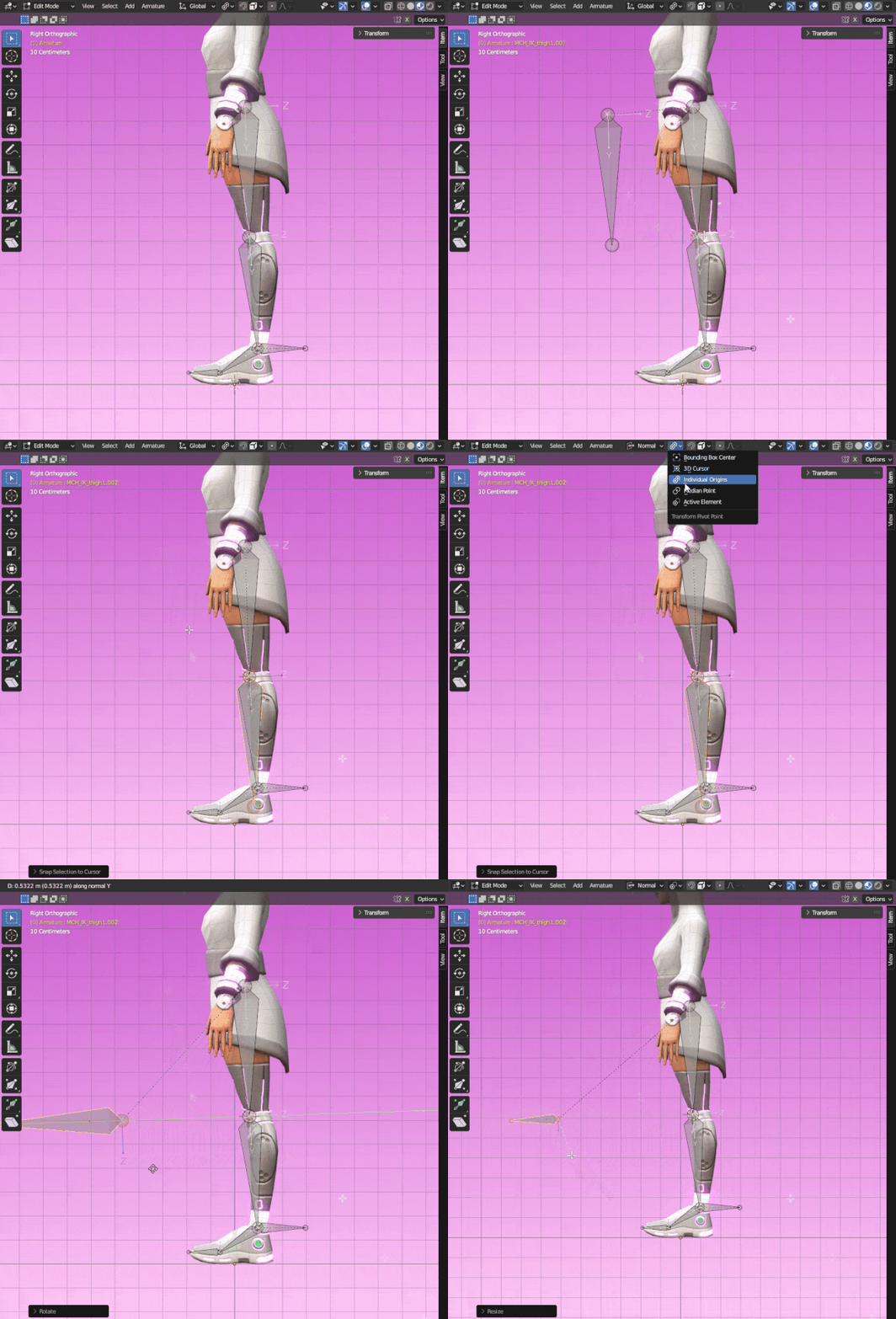
Creating a Pole Target.
Back into Pose Mode, select the shin again and go to the Bone Constraint Properties. For Pole Target select Armature and for Bone, select the pole target one you just created. If you show the deform bones, you will see that the pole target rotated the IK a little.
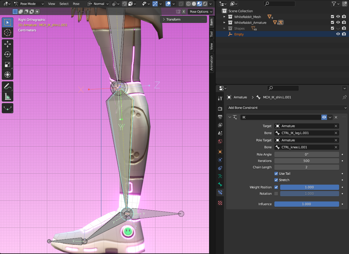
IK chain and deform bones are not aligned anymore because of pole target.
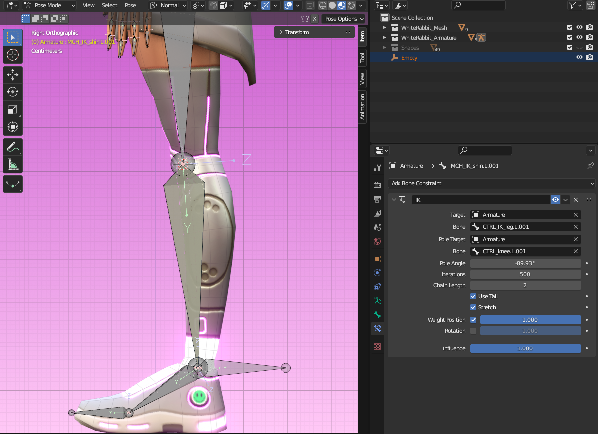
The rotation can be fixed by changing the Pole Angle.
That can be easily fixed by changing the Pole Angle. Usually -90° will do the trick, but you can always adjust it manually to make sure they are perfectly aligned.
Finally, make both the IK bone and the pole target chilld of the root bone by selecting them both, then the root, press CTRL+P > Keep Offset.
Move the thigh and shin to another layer since you won’t need them for animation, they are just part os the IK setup.
Binding Deform Bones to Non-Deforming Ones #
The IK chain is all set up, but it should drive the deform bones and right now that’s not happening, but you can use constraints to fix that. In Pose Mode, select a bone from the IK chain first and the respective deforming bone last, press CTRL+Shift+C and select Copy Transforms. Do that for all the bones, which in the example are thigh, shin, foot and toes. The deform bones will have a green color to them, which means that they have a constraint. If you click on Bone Constraint Properties, you can see which constraint is being used and what bone is driving it.
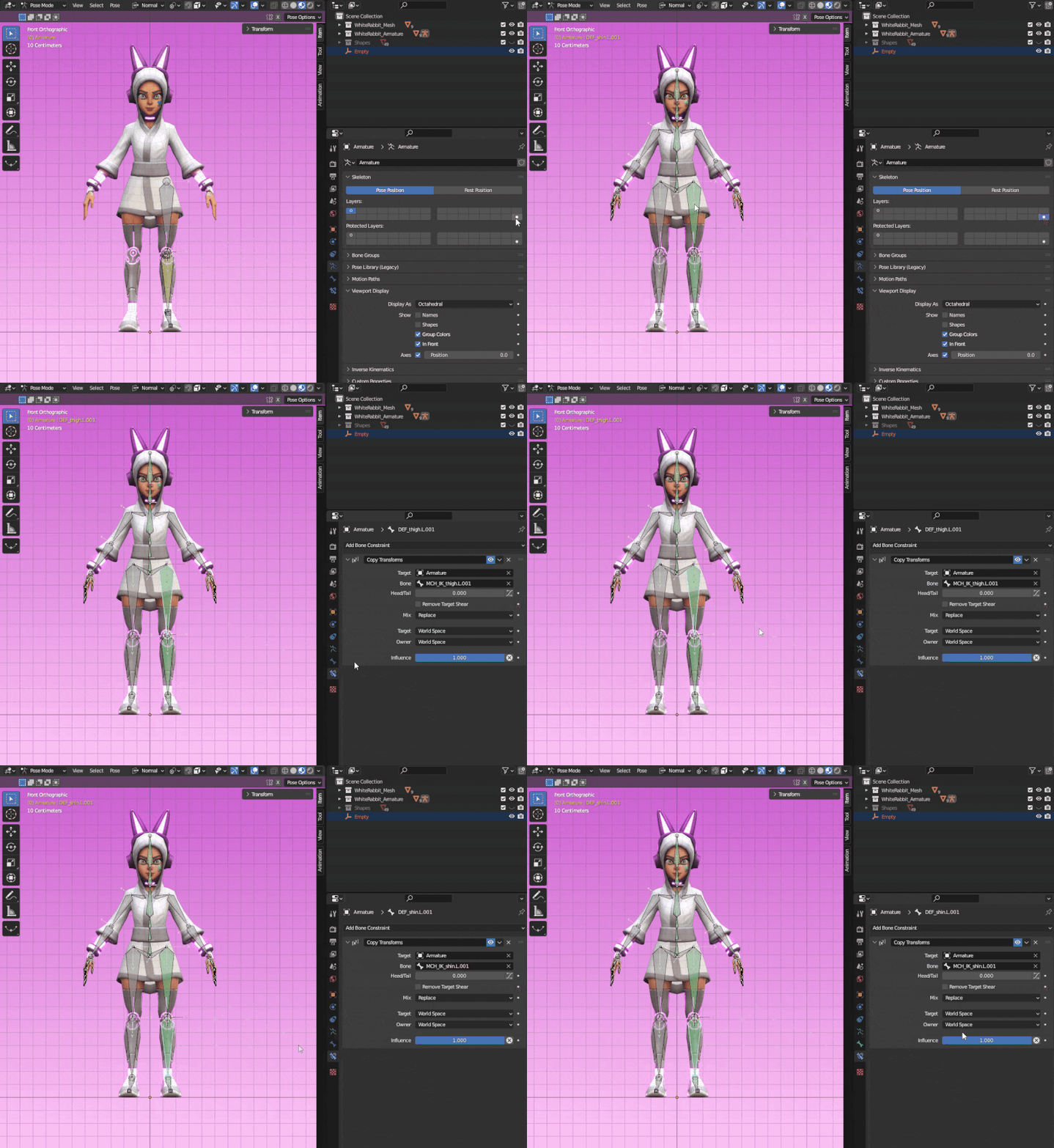
Green bones have constraints. You can check them in Bone Constraints Properties.
💡 Tip: You don’t have to set up the IK all over again for the other side. In Edit Mode, just delete all the bones from the side that doesn’t have the IK, then select all the deforming bones and IK chain that you want to mirror, right click with the mouse and select Symmetrize. It will not only mirror the bones, but also all the constraints!
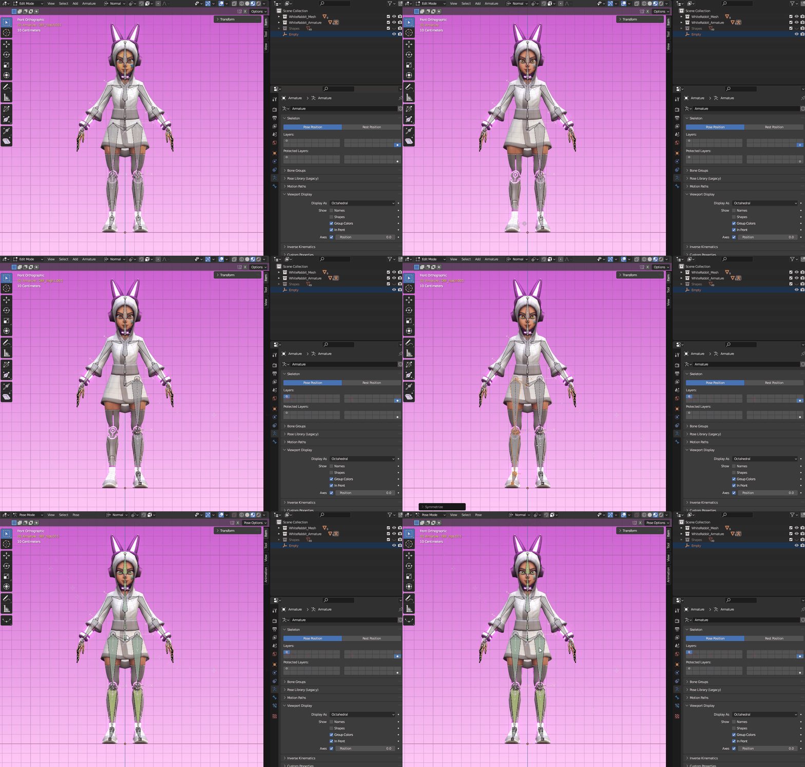
Use the option Symmetrize to mirror constraints too!
Non-deforming Skeleton and Controls** #
It’s good practice not to animate directly the deforming bones since you could end up breaking the rig and adding constraints to the deforming armature will affect the hierarchy and bone behaviour when exported.
The solution to this is to create a non-deforming skeleton that will drive the deforming one through constraints, and that can be animated safely, without risking breaking anything. You can also customize their shape to make it easier to identify a bone’s function. They will be the controls for your rig.
The process for this is pretty much the same done for the IK setup. Duplicate all the bones (except the IK setup) with Shift+D and move them to a different layer by pressing M and picking another slot. Rename them all by adding Control_ or CTRL_ as a suffix so you know these are part of the controls hierarchy. Press A to select all them and in Bone Property, press and hold Alt and uncheck Deform.
Now you’ll have to add constraints to bind the two skeletons together. To make this process easier, you can change the bone shape by clicking on Object Data Properties and, under Viewport Display, change Display As from Octahedral to B-Bone. Then, press CTRL+Alt+S to scale the bones up a little bit so their are bigger than the original ones.
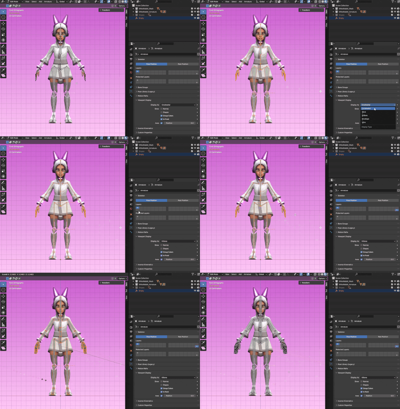
Change the bone shape and scale them up so it’s easier to differentiate between the two skeletons.
For the constraints, select a control bonefirst and the respective deforming bone last, press CTRL+Shift+C and select Copy Transforms. Do that for all the control bones.
You can separate the control bones into different groups and assign colors to them. Go to Pose Mode > Object Data Properties > Bone Groups. Click on the + icon to add a new group, rename it as you see fit and select a color for it. Then, select the bones you want to be part of that group and click on Assign. You can create as many groups as you like to keep everything organized. You can also move different bone groups to different layers.
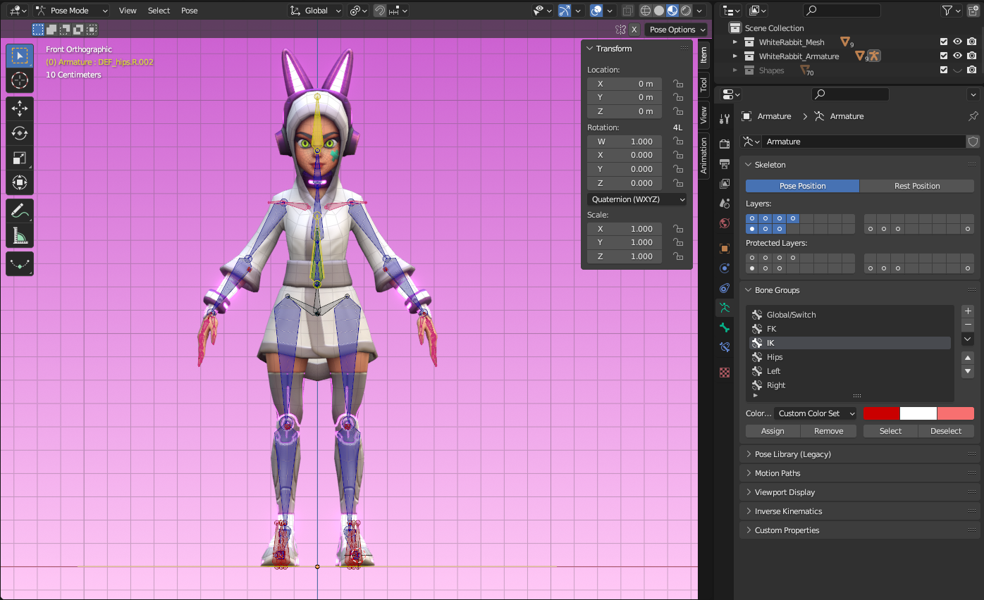
Bone groups will help you keep your rig organized and more intuitive.
An extra way to improve your rig is to customize the shape of the bones. To do that, go to Object Mode, press Shift+A to ad a mesh, like a circle, for example. To keep everything organized, create a collection for your shapes and move there the circle you just created. Go back to Pose Mode and, in Object Data Properties > Viewport Display check Shapes. Select the bone you want and then, in Bone Properties, click on Viewport Display > Custom Shape. In Custom object, select the circle in the outliner.
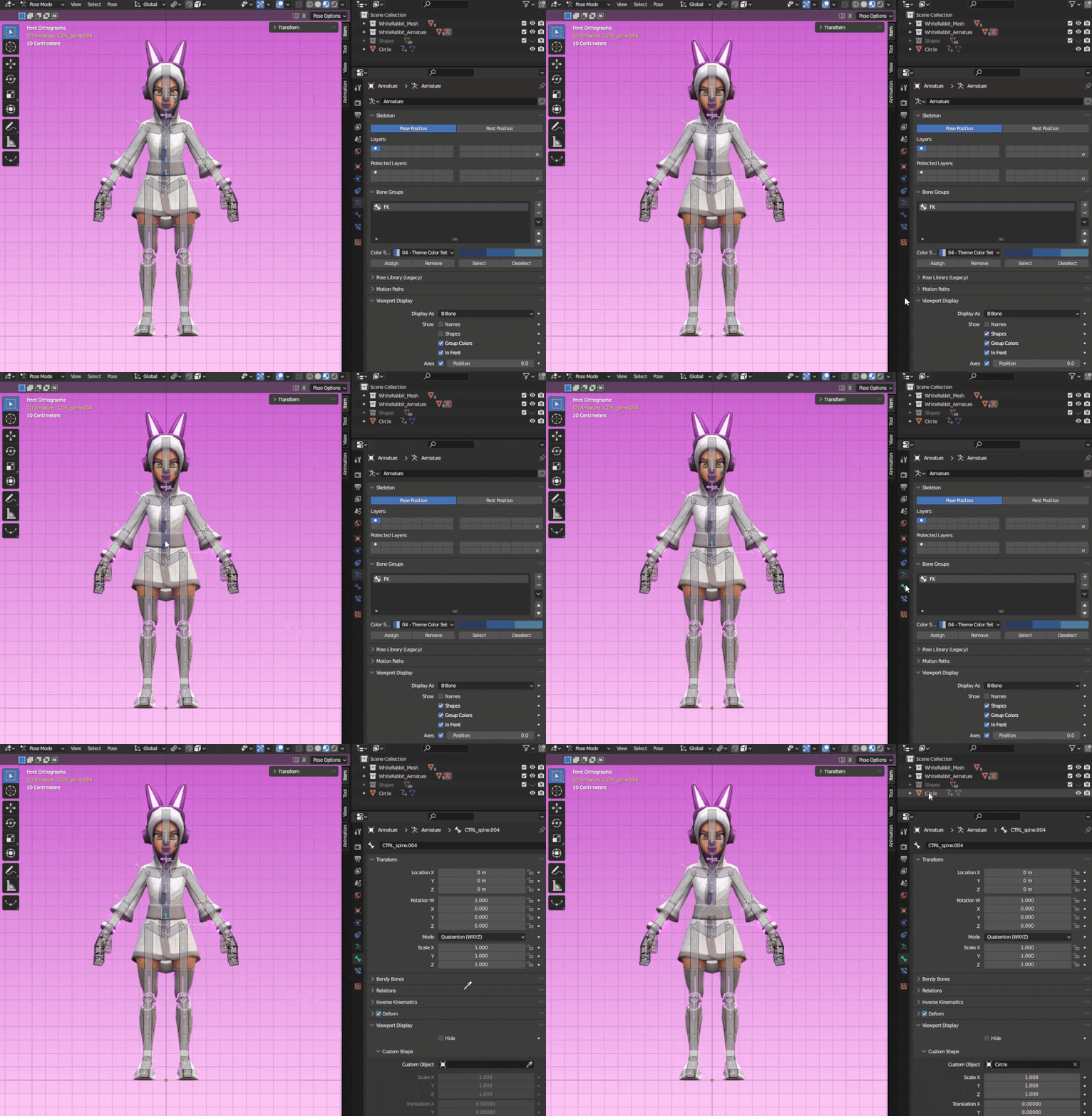
Customizing the bone shape.
If the shape feels off, you can always edit it in Edit Mode, as shown below. Make sure the shape has the same orientation os the bone.
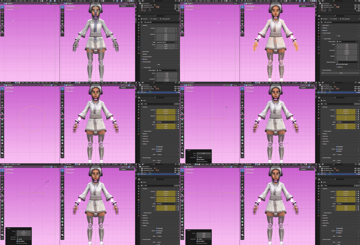
Edit the shape in Edit Mode.
Create different shapes for different controls according to their function to make your rig more intuitive.
And that’s it! With all this information you’re ready to do a basic rig!